BMP into Eagle
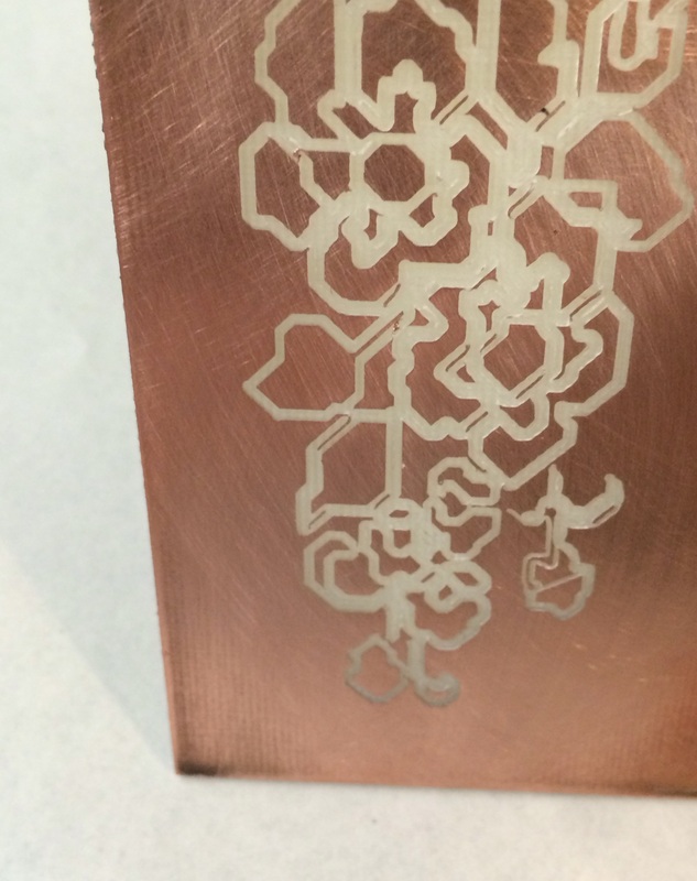
With a little help from this instructable, I brought an image of a piece of lace into Eagle with the plan of etching the image on the Roland. I drew out the traces by hand, the same way I would for etching a circuit, and then let the CNC work its magic. For my next try I may increase the bit size and try and get the image a bit clearer, but for a first test I was pretty happy with it.

|
|
Surface Mount
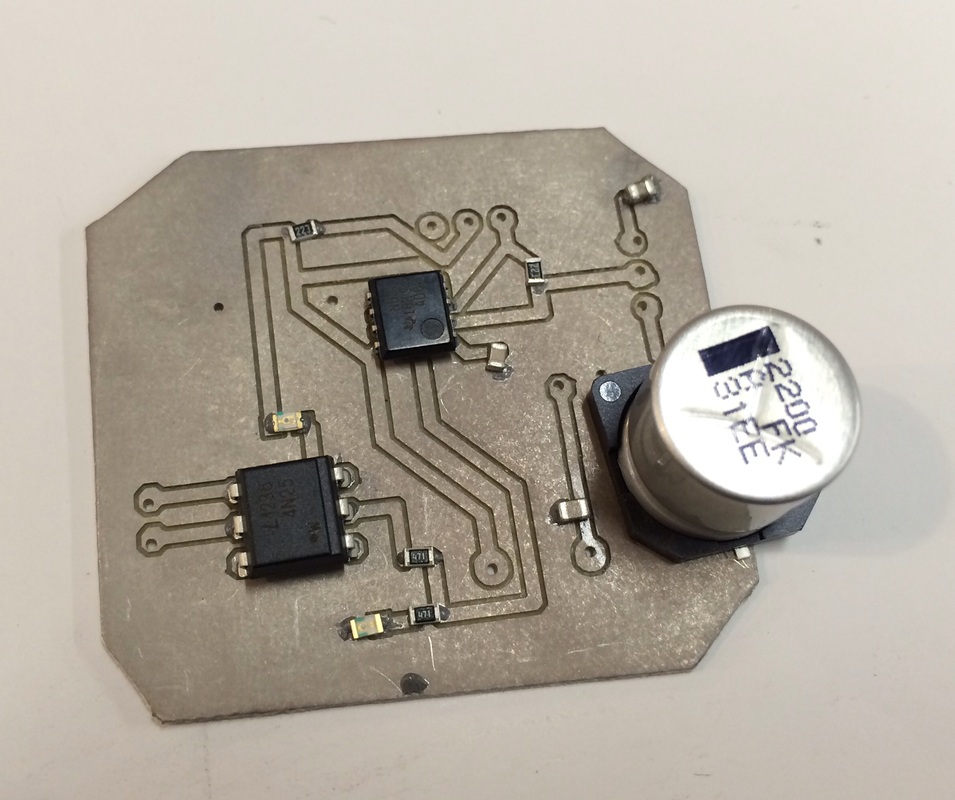
After a couple minor changes to my schematic, I was ready to try a surface mount version of my intervalometer. Using the Roland I milled out several boards knowing that surface mount circuitry will probably take a couple of attempts.
I then took my board and let it sit in a solution of tinnit for a few minutes. This changes the board to the silver you see below, and makes soldering surface mount components a little easier. This circuit has several switches and dials, so there are still a number of through hole components to integrate. The whole circuit is less than 2" square.
Roland Milling Machine
After I got my circuit working on my breadboard, and made some alterations, I brought it over into Eagle to layout the file.
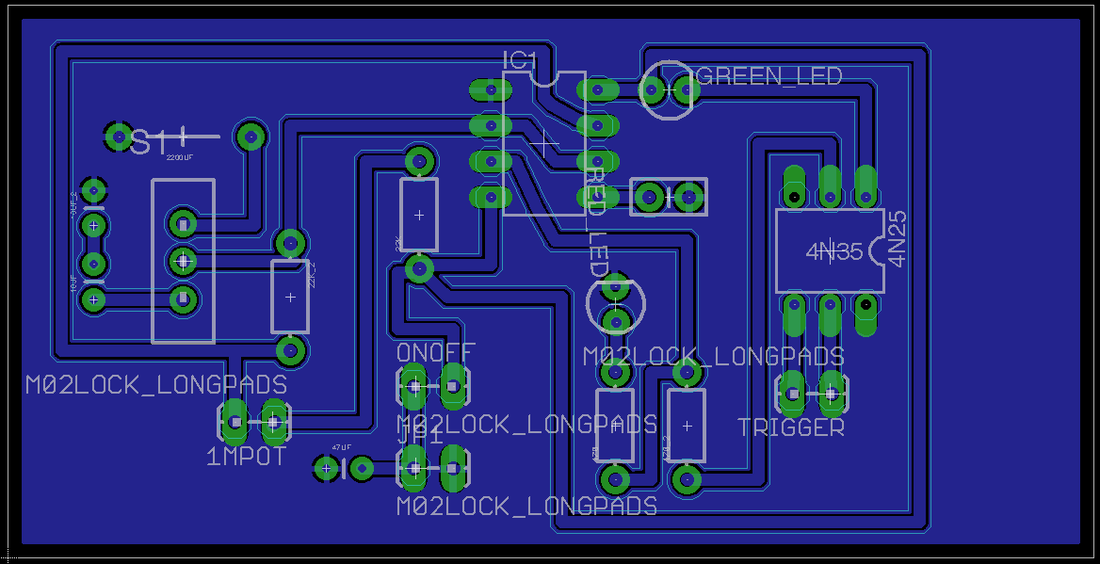
From there I brought the files over into our Roland milling machine, which made a beautiful board, although sadly it wasn't properly mirrored, so my ICs are backwards. I also realized some other changes I would like to make, so this was a good first round draft.
Adjusting Time Lapse
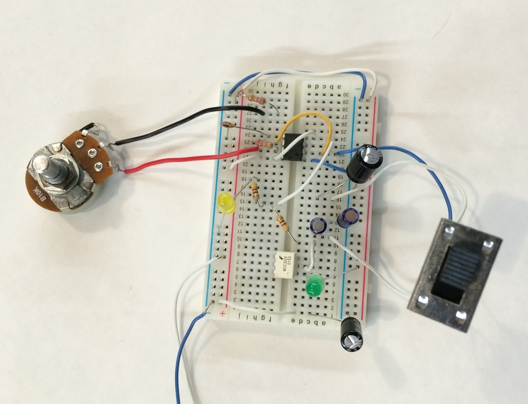
Today I hooked my circuit up to a simple Arduino sketch in order to track the amount of time between 'shots' or in this case, the amount of time between the LEDs lighting up. Increasing the size of the capacitor slowed down the frequency with which it would trigger the LED. I had originally started with a 220uF capacitor- by moving up to a 470uF I slowed the shot frequency down to once every 10 minutes, and my final jump up to a 2.2MF capacitor brought me all the way down to one trigger per 67 minutes! For a slow plant growth time lapse this should work great!
Intervalometer Test
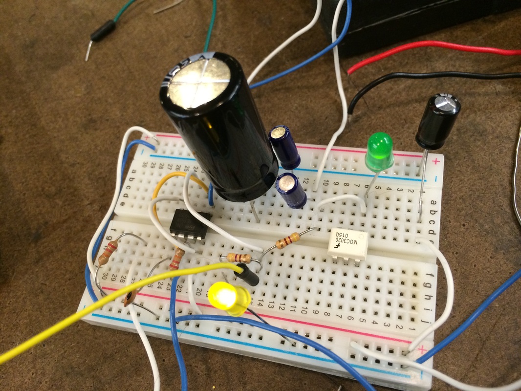
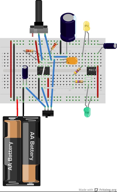
I'm starting to work on an intervalometer circuit for some time lapse photography - there's some really great documentation on the process for the Less is More intervalometer. I've got everything up on the breadboard, and should be receiving a cable to link to the camera in the next couple of days. Until then the yellow light turning on stands in for the camera firing, and the potentiometer and switch determine the length of time between shots. I may also test swapping in some larger capacitors to allow for a longer delay between photos.
Surface Mount
For this very simple LED circuit I'm using 0603 resistors. This image is actually two separate circuits, the bottom was used as a tester and was populated with 0 ohm resistors. The LED and the battery wires are both through-hole components.
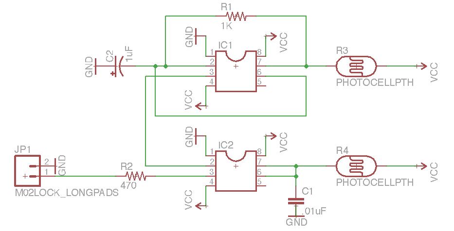
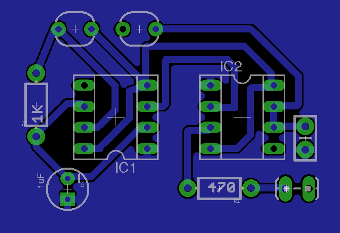
Getting started with Eagle
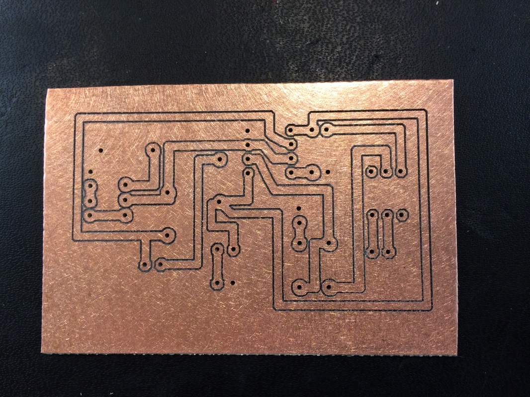
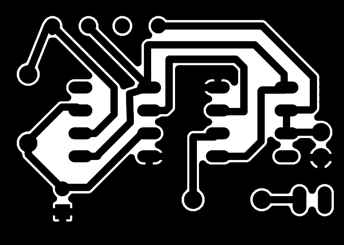
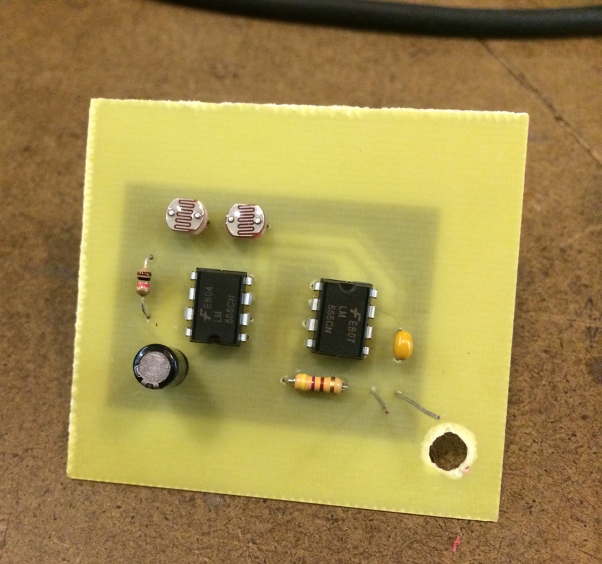
This project is the schematic and board layout for a light controlled theremin using two 555 timers.
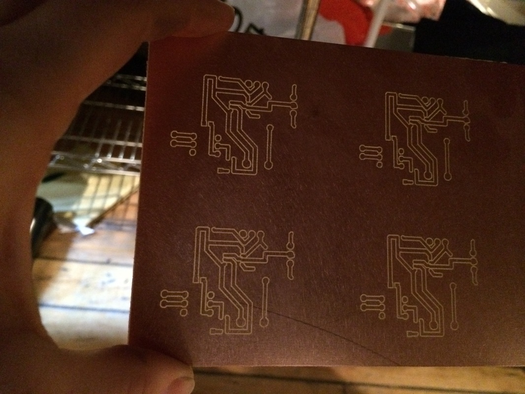
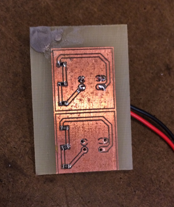
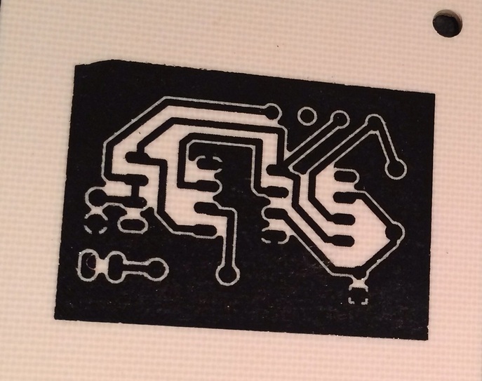
After printing out the board layout onto PCB paper, the ink is then heat transferred to a copper sheet, and acid etched in ferric choloride. the acid eats away the copper, leaving the ink covered traces behind.
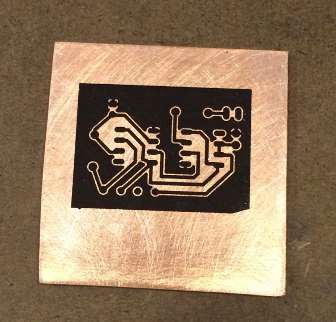
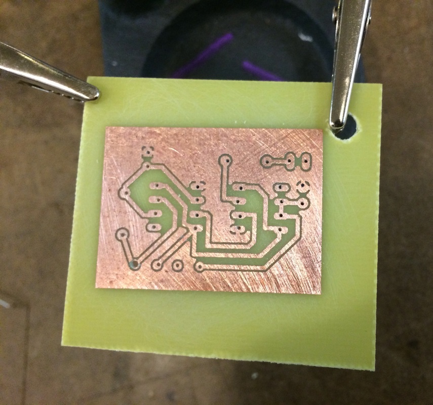
After the acid bath, the ink comes off with a little light sandpapering. This particular board is for through hole components, which I drilled out using a tiny dremel bit.
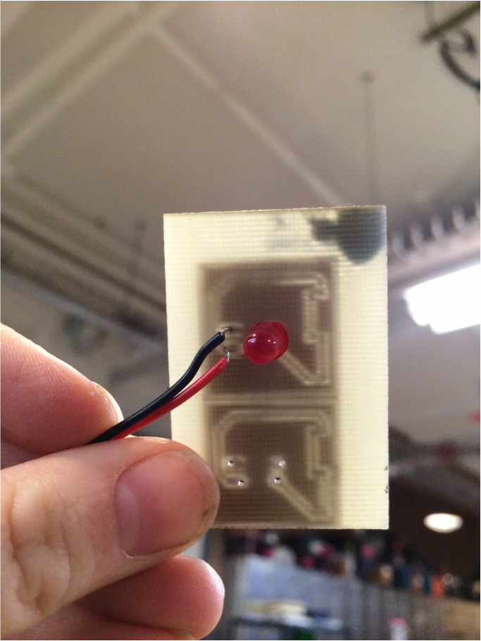
The board fully populated and soldered.
A final video of the light theremin in action.
